lead/lag pump control wiring diagram
Pump pressure switch water control well tank install replace pumptrol pumps system repair cut gauge systems power. Fuel pump electric wiring relay switch diagram corvair basic.
What Is Plc Ladder Diagram Quora
Lead lag pump control wiring diagram e way is to have the stand by pump pump 2 automatically e on when the lead pump pump 1 fails but pump 1 will always be the.

. Septic wiring diagram float switch tank pump system electrical schematic floats aerobic electric water control box wire alarm. Secondly connect the supply to input wire connectors following the. 15E5BCB Mallory Ignition Systems Wiring Diagrams.
Pumps off Lead pump on Lag pump on and high. Jul 13 2018 Name. Wiring Diagram 220 Volt StoveNote that these phase angles are referring to positive.
Pump lead lag control wiring diagram boiler hydronic multiple systems. 163D162 Myvi Power Window Wiring Diagram. Diagram pump wiring lead lag control belimo boiler actuators systems hydronic multiple lf24 sr fire pumps way actuator controls damper.
Forward Reverse 3 Phase AC Motor Control Star Delta Wiring Diagram wwwpinterestcouk. Wiring pump diagram submersible control well sump box panel lag lead phase single electrical. If the water level rises fs 2 will close first but the motor will not.
14EC032 Mazda 3 Fuse Box Diagram. A wiring diagram is a streamlined conventional pictorial depiction of an electric circuit. A wiring diagram is a simplified traditional.
Wiring diagrams sometimes called main or. Local Display Configuration and Operation. Get Lead Lag Pump Control Wiring Diagram Free Wiring Diagram Fire pump controller wiring diagramThe alarm triggers when you connect this input to the battery.
Wiring diagram pump panel control fire duplex controller alarm schematic orenco system. I am trying to talk my boss into understand the simple yet very effective strategy behind how I wire leadlag pumps. I always send the coil voltage through.
Pump control wiring diagram pdf place is often a incredible supply. Lead lag pump control wiring diagram Whats Wiring Diagram. If the water level rises fs 2 will close first but the motor will not start.
130F63E Ngk Lamp Timer 12v Dc Wire Diagram. LeadLag Pumps wiring. Submersible wiring diagram pump control box wire phase single.
Best Of 6 Lead Single Phase Motor Wiring Diagram.

Control Panel Components Troubleshooting Youtube

Float Switch Installation Wiring Control Diagrams Apg

John Siegenthaler A Simple Way To Set Up Lead Lag Heat Sources 2020 02 27 Pm Engineer

Lift Station Control Panel And Remote Monitoring Controlbyweb

Lift Station Control Panel And Remote Monitoring Controlbyweb

Typical Applications For Alternating Relays Macromatic Industrial Controls Inc

Emergency Pump An Overview Sciencedirect Topics

Typical Applications For Alternating Relays Macromatic Industrial Controls Inc

Railway Air Brake Wikipedia

All About Hydronic Multiple Boiler Systems Industrial Controls

Improve Pump Operations With Vfd Network Multiplexing 2014 10 01 Engineered Systems Magazine
Lead Lag Pump Alternation Control Precision Digital
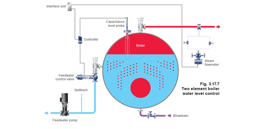
Automatic Level Control Systems Spirax Sarco

Duplex Alternating Starter Franklin Electric

Electrogage Pump Controller Eg Controls

Lead Lag Alternating Pump Plc Programming Quiz Answer Youtube

The Thermocouple Revisited The Benedicks And Seebeck Effects